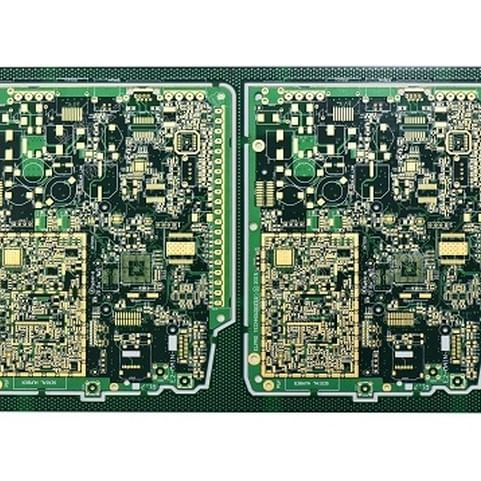
There are many technical differences between 5G cellular technology and previous mobile communications, and these differences will certainly affect the application and selection of PCBs and materials.5G applications are typically divided into sub-6 GHz bands and millimeter wave bands. Most of the initial deployments were based in the sub-6 GHz band; while, the majority of the deployments are in the sub-6 GHz band. With the development of millimeter wave systems, the millimeter wave band will be increasingly used in the future. 5G has the advantage of higher data rates and lower latency.

The boom in 5G technology will enable enhanced mobile broadband (eMBB), massive Internet of Things (MMTC), and ultra-reliable low-latency communications (uRLLC). PCBs associated with 5G applications will have higher levels of integration and more functionality, thus requiring higher PCB design requirements and a broader portfolio of circuit materials.
PCB heat management consideration
5G technology may lead to more PCB heat management issues for certain circuit functions. The heat generated by the PCB is usually related to insertion loss. Basically, circuits with higher insertion loss will generate more heat. Once heat is generated, it is important to direct the heat efficiently to the heatsink structure for heat dissipation. PCB materials to consider in this case material properties include loss factor and thermal conductivity.
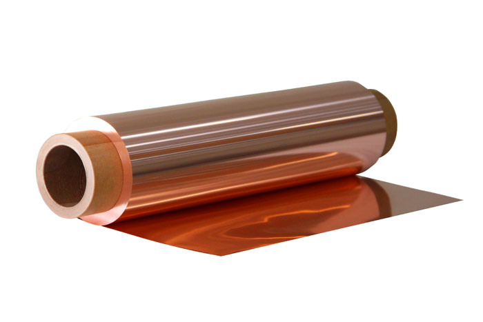
Low loss high frequency circuit materials have low insertion loss and therefore generate less heat. These high-frequency circuit materials are usually those with a lower loss factor (Df) and are usually made of copper foil with a smoother surface. It is well known that the surface roughness of the copper foil affects the insertion loss, and a low-profile or smooth-surfaced copper foil will produce less insertion loss. The copper foil surface roughness referred to here refers to the copper foil surface roughness at the interface between the HF laminate substrate and the copper foil.

Dissipation Factor (Df) Consideration
Df is the material loss tangent. It is not easy to determine if a laminate is low Df, which is very dependent on the circuit type used in the 5G system. Typically, a high frequency laminate should have a Df of 0.004 or less. For 5G applications below 6 GHz For 5G applications below 6 GHz, this is a good general Df value; however, at millimeter wave frequencies, a lower Df value may be required.
Thermal Conductivity Consideration
Another important circuit material property for some 5G circuits is thermal conductivity. Using a high thermal conductivity High frequency laminates are very beneficial for thermal management in 5G applications. In general, a laminate with a thermal conductivity of 0.50 W/m-K laminates are considered to be good thermal conductors. There are some high frequency, low loss laminates with this thermal conductivity. However few low-loss laminates have higher thermal conductivity.
RF PCB Material Selection - Rogers PCB
A newly released material from Rogers, the TC350 Plus laminate, offers an excellent combination of low loss and high thermal conductivity. TC350 Plus laminates have a Df of 0.0017 and a thermal conductivity of 1.24 W/m-K tested at 10 GHz. This is typically used in 5G power amplifier circuits that are more sensitive to thermal management. In addition, the antenna assembly's feed In addition, circuit structures such as feeder sections of antenna assemblies and others may also have thermal management issues.
Dk is the material relative permittivity. 5G antenna structures typically use low-loss materials with low Dk values. As with all other circuit designs, there are many tradeoffs compromises, and antenna circuits often use materials with lower Dk to obtain more efficient radiation. Taking many factors into account many factors, typically antenna circuits will use circuit materials with a Dk value of about 3.
Rogers' RO4730G3 laminate is suitable for a wide range of 5G antenna applications because it has a nominal Dk of 3.0 and Df of 0.0029 when tested at 10 GHz and a very good temperature coefficient of dielectric constant (TCDk). TCDk is an important characteristic for 5G antenna applications because these circuits will likely be exposed to a certain temperature environment. is a material property, which is a property of the material Dk that varies with temperature and is common to all materials. For laminates, a good TCDk value is 50 ppm/°C, which is ideally close to zero. The TCDk value of RO4730G3 laminate is 26 ppm/°C.

Final Thoughts
When designing circuits for 5G PCB applications, many factors need to be considered, such as material properties and interactions with other PCBs using material interactions. It is highly recommended to work closely with material suppliers when considering high frequency materials for 5G applications.
It is highly recommended to work closely with PCB manufacturers when considering high frequency materials for 5G applications.
- Comments(7)
R****Kja
Jun 15.2024, 19:33:13
L****llo
Apr 10.2024, 15:55:14
M****Ali
Apr 01.2024, 16:50:42
M****Ali
Mar 24.2024, 18:57:06
**
Mar 17.2024, 19:32:30
m****lam
Mar 13.2024, 16:22:27
**
Mar 11.2024, 15:40:29
